Automatic Virtual Slide Analysis Using Computer Vision
There are many exciting image analysis projects being developed at the University of Leeds, thanks to the ongoing collaborations between the Section of Pathology and the School of Computing. Some of these projects are described below.
Algorithm Development and Resources
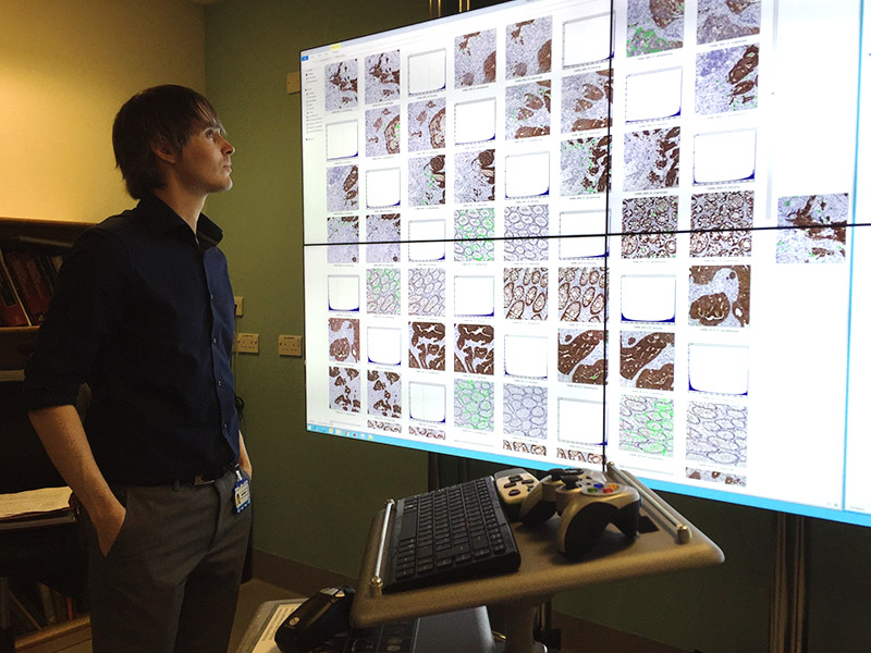
Alex Wright viewing image analysis results on the Virtual Pathology Powerwall
The Virtual Pathology department at the University of Leeds currently has 239.6TB of digital slides (591,091 images), which facilitate almost all of the computing based research projects undertaken here.
Algorithms are developed using an array of high performance virtual machines, and devloped algorithms are deployed on dedicated servers in order to be run with accompanying web services so that researchers can use them. Also, the University allows shared access to their high performance computing clusters, which are capable of parallel processing, and have over 3000 processors!
One of the foremost human-computer interaction experiments developed within the department (known as the Virtual Pathology Powerwall project) is also used to help display large amounts of image processing results for rapid visual assessment of algorithm performance (see image above).
Stain Quantification
The quantification of the amount of stain taken up by tissue is an important visual characteristic used in histopathology to understand the formation of disease. Different types of stains are applied to tissues in order to highlight areas which help to diagnose a specific disease or predict its behaviour or response to therapy.
There are many types of stains that highlight many different tissue features, but for this section, we will be talking about Haematoxylin (H), Eosin (E) and Diaminobenzidine (DAB). Typically tissue is stained with a nuclear stain (H), and a counterstain (E or DAB), depending on the type of analysis required. In some cases, multiple complementary counterstains are used to provide more visual information to the pathologist.
Combining stains on tissue means that where two or more stains are present, the appearance gets darker (due to subtractive colour mixing). The image below illustrates how the colours are mixed when two stains are applied (H&E on the left and HDAB on the right).

Illustrations of Subtractive Colour Mixing to form Colocalised stains (H&E left, HDAB right)
Haematoxylin and Eosin
Haematoxylin (H) and Eosin (E) are stains used together in order to highlight structural elements of tissue, which help pathologists observe important features of disease such as the size, shape, position and the type and density of the cells of which it is made.
When analysing a digital slide stained with H&E, the Haematoxylin stains nuclei a blue colour, and the Eosin stains cytoplasm and extracellular proteins a pink colour. The areas of tissue where the stains appear together is known as colocalisation, and will appear purple, due to subtractive colour mixing.
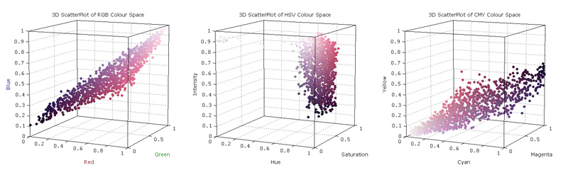
3D scatter plots of pixel colours in H&E stained tissue images (left to right: RGB, HSV and CMYK colourspaces)
The colours of each pixel in a digital slide image are expressed in the standard RGB (red-green-blue) colourspace, and each of the three values can be transformed to express other colourspaces. In the image above you can see the same colours from a H&E stained digital slide expressed in red green blue (RGB), hue, saturation intensity (HSV) and cyan, magenta yellow (CMY) colourspaces.
These colourspaces can be transformed further with respect to predefined colours - instead of a 3 values representing the amount of red, green and blue, the colourspace can also be transformed to represent staining intensities, such as Haematoxylin, Eosin and Diaminobenzidine (DAB). When these stains are used as colour vectors, each staining component can be represented individually. Using this method, we can digitally separate stains from each other (see below).
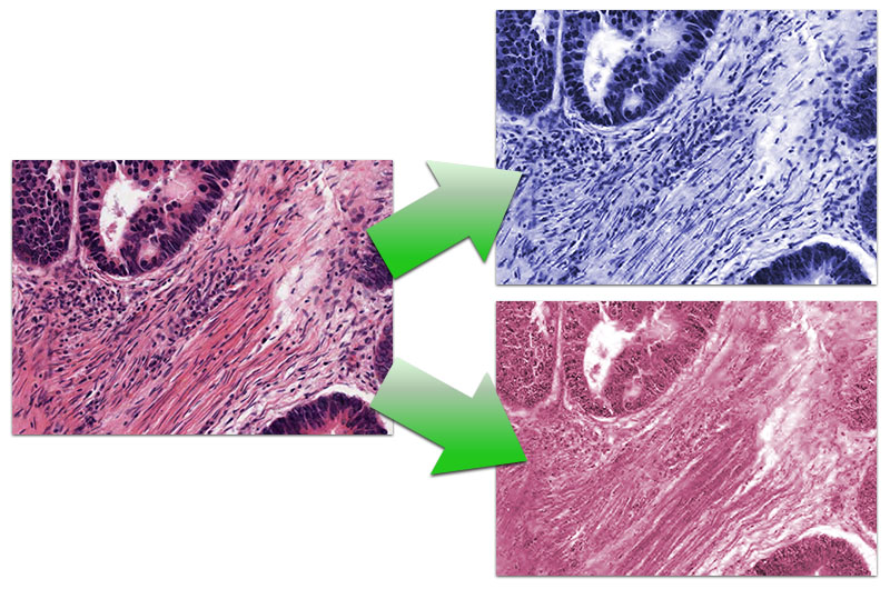
Colour deconvolution separating a H&E stained image into individual staining components
(colours in result images are simulated)
By applying this technique to whole slide imaging, we can generate heatmaps that show densely clustered areas of nuclei.
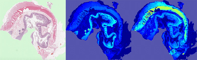
Heatmaps of staining intensities for separated haematoxylin and eosin stains
Immuno staining
Immuno staining is used to highlight certain proteins expressed within a tissue. The tissue is primed with antibodies which bind to specific types of protein within cells. A secondary antibody is applied, which oxidises a stain called Diaminobenzidine (DAB) and turns the affected areas brown.
Immuno staining is useful for identifying specific components of a disease, and as such, quantification of the presence of such staining is an important metric for analysing cancer. In the 3D graphs below, you can see an image stained with H-DAB in the RGB and HSV colourspaces.
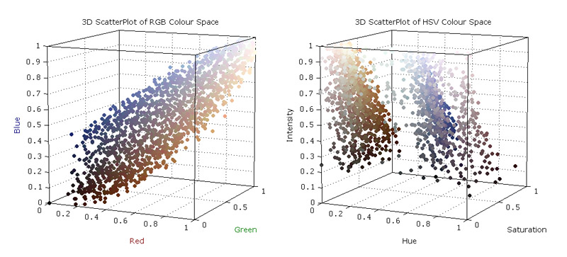
3D scatter plots of pixel colours in HDAB stained tissue images - RGB (left) and HSV (right) colourspaces
By applying this form of quantification to whole slide imaging, we can generate heatmaps of the presence and intensity of the brown stain (below). From here, we can identify specific areas of tissue and patterns of staining.
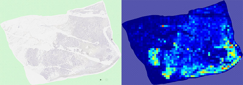
Heatmap of area detected (per sqaure block) of specific stain, identified by colour thresholding & deconvolution
Using immunohistochemistry, we can identify and quantify areas of tissue that are cancerous, and use the visual characteristics of the cancerous areas to predict how the cancer will grow, and how it will respond to therapy.
Stain Colocalisation
Using immunohistochemistry, we can identify and quantify areas of tissue that are cancerous, and analyse their shape, density and form. We can also examine subcelluar component of the image by using the simple inference that if we can detect entire cancerous cells using the brown DAB stain, and we can highlight nuclei using H, then we can use these areas to mask each other, and find out information about the content of DAB within individual nuclei (below, middle right), or just the cytoplasm (below, right).

Cellular colocalisation of H and DAB stains - after deconvolution, the cell can be broken down into the nuclear and cytopalsmic stain areas, and then using the two areas as an image mask, we can analyse the nuclear or cytoplasmic areas of the cell individually.
Identifying Prognostic Features - Tumour:Stroma Ratio
Stereology
Pathologists use the visual features of cancer tissue to assess the aggressiveness of a cancer and how it will respond to treatments. One such prognostic feature of Colorectal cancer is the ratio of Tumour tissue, to the connective tissue called Stroma. This feature was found to be prognostic by researchers at Leeds using the RandomSpot stereology system, and further use of this system has shown that the Tumour:Stroma ratio is prognostic in breast, oesophageal and pancreatic cancer as well.

Example of the RandomSpot stereology tool sampling coloretal cancer
Using existing data from these studies, the co-ordinates of each sampling point can be used to extract images at their locations, with their associated classifications, given by the original pathologists that scored them. The image below illustrates the types of tissue that can be found within colorectal cancers.
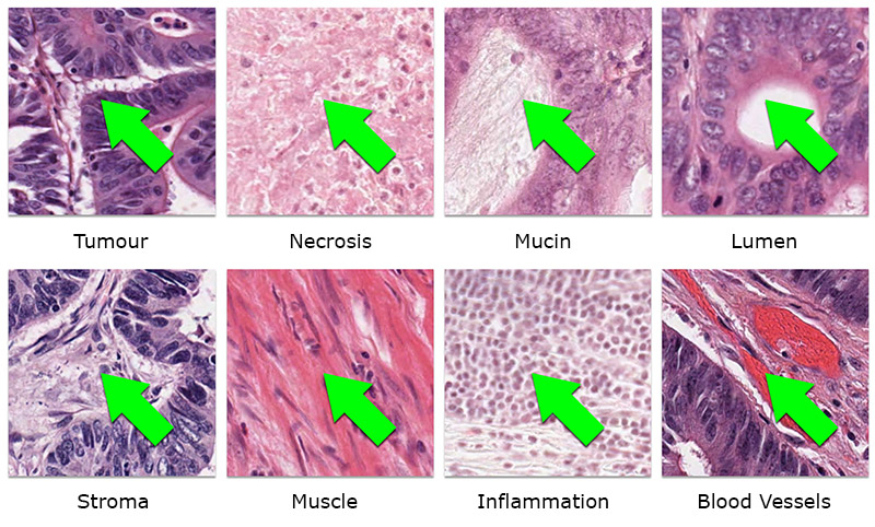
Examples of different types of tissue found within the cancer being analysed (bowel), that the pathologist can assign to each sampling point
By extracting these sampling points as images, we have the potential to generate statistics from each image and assign them to a classification. This forms the basis of artificial intelligence, and allows machine learning algorithms to form associations between visual characteristics and tissue types, so that unseen images can be classified based on the predictive values that the algorithms generate.
This opens up questions about what sort of image statistics should be used, and what size images are appropriate for generating features from.

Examples of multiple image sizes using the same sampling co-ordinates (left to right: 64px 256px 1024px)
By using the spots generated by the RandomSpot software, we can extract images of any size, using the spot coordinates as the centre. The examples above all use the same spot coordinate but the different sized images contain different proportions of tissue in each. Since the classification for each image is the same, this creates problems learning the appearance of tissue types.

Results of Machine Learning Agreement per Image Patch Size compared to human agreement per patch size
The algorithm agreement declines as patch size increases, as opposed to the pathologist agreement, which increases when increasing the image size. This implies two things: 1) the algorithm decreases in accuracy because the larger patches are more likely to contain more than one type of tissue, which affects the feature vectors 2) the human accuracy increases on the bigger images because the surrounding visual information (context) is important for basing diagnostic decisions.
The conclusion from these results is that larger images needed to be used for automatic analysis, but they need to be divided so that each segment in the image only contains one tissue type.
Unsupervised Segmentation
Unsupervised segmentation allows the image to be divided into non-regular areas which should traverse object boundaries. This means that each segment should only contain one type of tissue, and therefore generate statistics that are truly representative of the tissue being analysed.
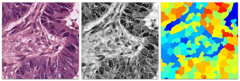
Over-segmentation of colorectal cancer using the SLIC algorithm
Automatic segmentation of colorectal cancer using the Normalised Cuts algorithm
Wright, A. I., Magee D. R., Quirke, P., Treanor, D. (2016) Incorporating Local and Global Context for Better Automated Analysis of Colorectal Cancer on Digital Pathology Slides 20th Conference on Medical Image Understanding and Analysis (MIUA 2016) Proc Comp Science. Vol 90, pp 125-131; doi:10.1016/j.procs.2016.07.034
Wright, A. I., Magee D. R., Quirke, P., Treanor, D. (2014) Towards automatic patient selection for chemotherapy in colorectal cancer trials Proc. SPIE 9041, Medical Imaging 2014: Digital Pathology, 90410A (March 20, 2014); doi:10.1117/12.2043220
Wright, A. I., Coe, A., Dattani, M., Toh, E., Hutchins, G., West, N., Grabsch, H., Magee D. R., Quirke, P., Treanor, D. (2012) Automatic Image Analysis to Calculate the Cancer:Stroma Ratio in Colorectal Cancer Presented at: Joint Meeting of the Pathological Society of Great Britain and Ireland and the Dutch Pathological Society. University of Sheffield, UK.
For more information, please see our publications
Identifying Prognostic Features - Tumour Budding
Under construction
Tissue MicroArray Analysis
Tissue MicroArrays (TMAs) are a high throughput method of analysing patient tissue. Cylindrical pieces of tissue are taken from patient biopsy samples using a hollow needle, typically 0.6mm in diameter. This tissue is pushed out of the needle and embedded into a paraffin wax block. The wax block is then sliced in the same way as normal biopsy tissue using a microtome, to create sections which are placed on a glass slide and then stained.

A simplified illustration of the TMA creation process
TMAi is a web based system designed to handle management and analysis of Tissue MicroArrays. By using image analysis to de-array TMA cores, the system automatically labels tissue images with identification labels, for quick access of large volumes of data.

The TMAi de-arraying process
The TMAi back end comprises of an open-standards compliant database, which means that data from TMAi can be exported into a published XML standard format, and shared with other systems that use the same.
After core images are assigned to identifiers, then can then be either manually analysed using the in built rapid scoring user interface, or users can make use of the automated stain quantification algorithms to analyse their entire dataset at the click of a button.
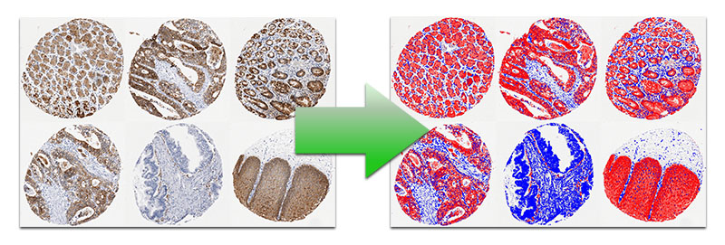
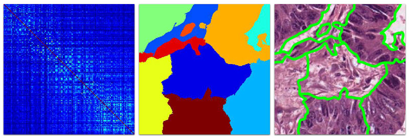
Automatic stain quantification performed on TMA cores
Using the stain colocalisation analysis (mentioned above), TMA cores can be analysed for both nuclear and cytoplasmic staining density and intensity. This intensity of stain can be compared to the standard immuno scoring method used by pathologists by grouping the results into one of four categories: no stain present, less than 33% stain, between 33% and 66% stain and over 66% stain (see boxplots below).


Automatic stain quantification performed on TMA cores
Wright, A. I., Hutchins, G. G. A., Randell, R., Quirke, P., Treanor, D. (2010) TMAi (Tissue MicroArray informatics): Using virtual slides and open standards to provide usability and interoperability for tissue microarrays in clinical trials. Presented at: 6th NCRI Cancer Conference. BT Conference Centre, Liverpool, UK.
Wright, A., Lander, J., Kaushal, S., Pan, T., Sharma, A., Wang, F., Kurc, T., Saltz, J., Quirke, P., Treanor, D. (2009) Utilising caGRID Infrastructure for Tissue MicroArray Analysis Presented at: Biomedical Informatics without borders: From collaboration to implementation. A joint conference of the U.S. National Cancer Institute and the U.K. National Cancer Research Institute Informatics Initiative. Wellcome Trust, London, UK.
Wright, A., Lyttleton, O., Lewis, P., Quirke, P., Treanor, D. (2009) TMAi | An open source Tissue Microarray database using published XML standards. Presented at: Biomedical Informatics without borders: From collaboration to implementation. A joint conference of the U.S. National Cancer Institute and the U.K. National Cancer Research Institute Informatics Initiative. Wellcome Trust, London, UK.
Wright, A. I., Magee, D., Quirke, P., Treanor, D. (2008) Automated scoring of Tissue Mircoarrays using virtual slides. Presented at: Joint Meeting of the Pathological Society of Great Britain and Ireland and the Dutch Pathological Society. University of Leeds, UK.
Nuclear Detection
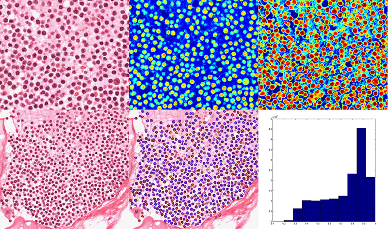
Lymphocyte cell detection using the Haematoxylin channel from the colour deconvolution process
Zhou, Y., Magee, D., Treanor, D., Bulpitt, A. (2013) Stain guided mean-shift filtering in automatic detection of human tissue nucleis. J. Pathol. Inform., vol. 4, no. 2, p. 6, 2013.
Bennett A, Zhu Y, Wright A, Verbeke C, Hodgkin L, Magee D, Spiers V, Treanor D (2009) A novel nuclear detection algorithm for the automatic analysis of immunohistochemistry staining. Presented at: Joint Meeting of the Pathological Society of Great Britain and Ireland and the Dutch Pathological Society. University of Cardiff, UK.
Liver Fat Detection
Ladislav Gubic 2007, Ben Tappin 2006


A virtual slide of liver tissue (left) shows areas of normal liver cells in pink and fat globules in white. Our algorithm detects the fat and produces a segmented image to indicate the size, number, and location of the fat globules.

The algorithm results (Y axis) correlate with the pathologist estimation of the fat present (X axis).

Running the algorithm on the whole slide allows visualisation of steatosis distribution in 2D. In the example below, fatty sparing adjacent to a tumour is demonstrated by whole slide image analysis (H&E stain of whole slide, left; heatmap of fat distribution, right)